« Connecting the Roland S550 Sampler to a VGA LCD MonitorSunday 5th July 2015 | ||||||
|
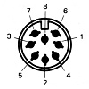
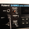
Why connect an external monitor As I mentioned in my Why I love my Roland S550 Sampler post, you don 't need to run the S550 through an external monitor to play music but it's pretty much impossible to sample new sounds and edit patches without the help of a display. You can easily hook up a monochrome display but the S550 is far cooler operated in 'full' colour on a 'Digital RGB' screen. So before I tell you how I got my sampler to display on my LCD monitor, I'll try to explain what's going on here ... RGB, CGA, VGA, ... ? Just like music, video colour signals come in digital and analog forms. Unlike music however, in the video world digital came first. Early digital colour screens had separate RGB - red, green and blue - signal connections but were only one bit - either on or off. This limited the total number of colours that could be displayed using those signals to eight combinations - black (000), red (100), green (010), blue (001), yellow (110), cyan (011), magenta (101) and white (111). This is what the S550 calls Digital RGB and is largely compatible with CGA. After CGA came EGA in the PC world where IBM increased the number of colours that could be displayed by varying the voltage on the RGB signals lines. This is referred to as analog because it used analogue voltages over the connecting cable produced by separate D/A converters for each colour signal. Of course, the pixel resolution increased as well. 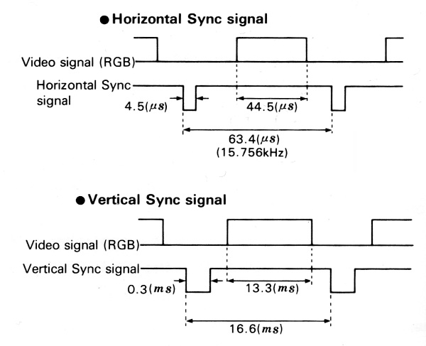 Digital RGB and CGA also send timing pulses / signals to synchronise the RGB colour information with scan lines on the monitor. There are separate horizontal and vertical sync signals which can be combined to a composite sync signal. Finding a compatible monitor at the time meant matching the sync speed of the device with the monitor. The chart above is from the S550 owner's manual and shows that the S550 generates a roughly 16kHz horizontal sync signal. 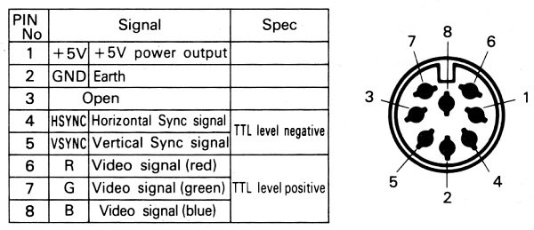 This chart is also from the S550 owner's manual and gives the pin-outs of the Digital RGB connection with a bit of an explanation. Don't worry too much about the 'Spec' column, digital signals themselves can be positive (0 = 0 volts, 1 = 5 volts) or negative (0 = 5 volts, 1 = 0 volts) and this is what the owner's manual is referring to as TTL level negative or positive. The RGB-25I cable from Roland had a built in inverter to swap the polarity of the sync signals but the CGA to VGA converter board I used handles the inverted signals no problem. Having +5 volts on the connecter wire is a bit non-standard but was probably used to power the RGB-25I inverter. One thing I have figured out from looking at the S550's circuit diagrams is that the above chart has an error! Pin 4 is actually a composite sync signal rather than horizontal sync as shown on the chart. As I said - most of this is sorted out nicely by the CGA to VGA converter board so don't get too hung up on the details. I have just included them here in case somebody is hunting the web for this info for another purpose. A suitable CGA to VGA converter board 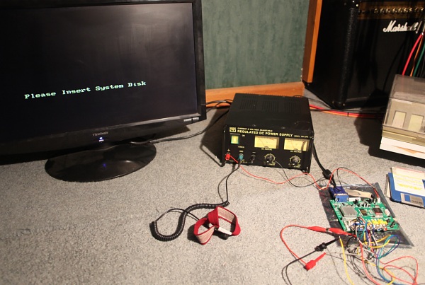 I bought my 'CGA/EGA/YUV to VGA Arcade HD-Converter PCB' board off of ebay for around US$40. It is a 'GBS 8200 V4.0' and I vaguely remember reading that some people had issues with pre-version 4 boards but I can't remember the details. It looks very similar to boards currently for sale and the specs don't seem to have changed. The specs say that the board can auto-configure to CGA with 14½ - 16½KHz, 23½ - 25½KHz and 30½ - 32½KHz ranges so that matches nicely. It even comes with the connector plug and cable that plugs into P11 on the board. As you can see from the photo, the board has a VGA connecter at the top left and the cable wanders behind my power supply over to the LCD monitor on the left. The power supply is a bit over the top but was easier to find than a plug pack around here. The anti-static strap is a good precaution when playing with circuit boards. Powering the board 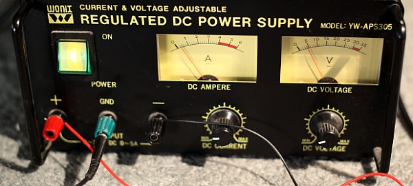 The power supply is generating around 5 volts and seems to be supplying about 250 milliamps. The specs for the board say it draws 2 amps at 5 volts and the board has markings saying that 5 - 12 volts is acceptable. There is also a DC regulator circuit on the board so 12 volts would probably work fine but I would look for a roughly 6 volt plug pack to run this from that outputs as much power as you can find - and then check it isn't getting too hot when you connect it all up. One thought I had was to run the board from the +5 volts supplied by pin 1 from the S550, but I wouldn't want to be drawing 2 amps from the S550 (or through the cable for that matter) so I haven't tried this. The biggest advantage would be one less power pack and the power switch on the S550 would then power up the converter board as well. Wiring the connector cable 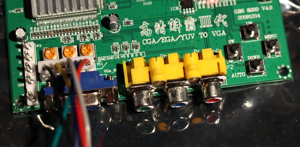 I used the supplied connector cable plugged into P11 (as you can see in the photo) to wire the board to my old monitor cable for the S550. If you don't have a cable for the S550 you will need to track down and wire an 8-pin DIN plug (readily available on ebay) with the pin-outs shown below (I have included the wire colours from my cable so it is easier to see what is happening in the photos): Pin 1 - Pin 2 - ground (black) Pin 3 - Pin 4 - composite sync (incorrectly labelled horizontal sync by Roland)(yellow) Pin 5 - vertical sync (white) Pin 6 - (red) Pin 7 - (green) Pin 8 - (blue) Here are the pin-outs for P11 - the 8 pin connector on the converter board in the photo (the wire colours in brackets are from the cable supplied with the board). The pin-outs are also marked on the board to the right of the plug. Pin 1 - ground (black) Pin 2 - ground (-) Pin 3 - vertical sync (yellow) Pin 4 - horizontal sync (-) Pin 5 - composite sync (grey) Pin 6 - (blue) Pin 7 - (green) Pin 8 - (red) 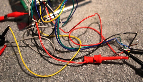 Now it's just a matter of connecting the correct wires together! I initially just twisted the wires together and insulated them with some clear sticky tape as you can see. S550 Pin 2 - ground (black) => P11 Pin 1 (black) S550 Pin 4 - composite sync (yellow) => P11 Pin 5 (grey) S550 Pin 5 - vertical sync (white) => P11 Pin 3 (yellow) S550 Pin 6 - (red) => Pin 8 (red) S550 Pin 7 - (green) => Pin 7 (green) S550 Pin 8 - (blue) => Pin 6 (blue) Adjustments and Configuring Power up your LCD monitor and the converter board first. You should see some Chinese text appear so the first thing you will want to do is configure the converter board language to English. These settings are retained when power is disconnected so you only need to do this once. Use the four push buttons on the lower right side of the board. 'Menu' displays this (in English): 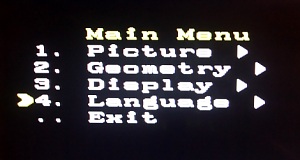 'Up' and 'down' scroll through the list and 'SW' sets options. Here are photos of all the sub-menu settings I used to get a fairly decent picture from the S550: 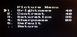 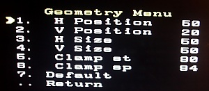 This depends on the LCD monitor you are connecting: 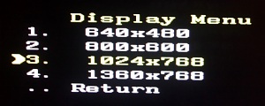 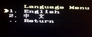 Pressing 'menu' again hides the menu. Now switch on the S550 and wait for it to ask for the system disk. With no menu displayed, press the 'down' button on the converter board to auto scan and configure for the S550. I don't think I needed to switch inputs using the 'sw' button but it is over a year now since I did all this so give it a try if you aren't getting any picture. 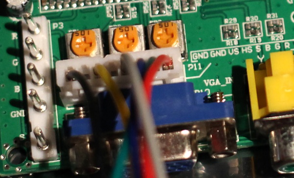 Just above P11 in the above photo are three orange trim pots (they may be a different colour on your board) that you can adjust to get the best possible colours - I think they all needed to be toned down a bit when I set mine up. The photo shows the final setting I chose. If you have an overall colour-cast you can correct it here but otherwise make sure you adjust all three pots by the same amount or you will introduce a cast. Image stability The 'Play' screen with 8 keyboards is the least stable screen that the S550 displays. It used to shimmer on the old RGB monitor I had and I always blamed the monitor, but as you can see the same issue shows up with the converter board so I now think it has something to do with the composite sync signal generated by the S550. It may only be my S550 that does this - but it is the screen I chose to fine tune the converter's settings on as it is the most troublesome so I recommend you do the same. Anyway - best of British and all that. I hope you can wade your way through all of this info to an amazing technicolor sampling experience. | ||||||
| ||||||
| Blog | ||||||
| Home · About Freudelheim · Blog Index | ||||||
| RSS Feed · Atom Feed · Twitter · SoundCloud · Graffiti · Medal of Honour | ||||||
| All content and images copyright © 2007 - 2016 Nate Marshall. Site Design by Nate Marshall |
